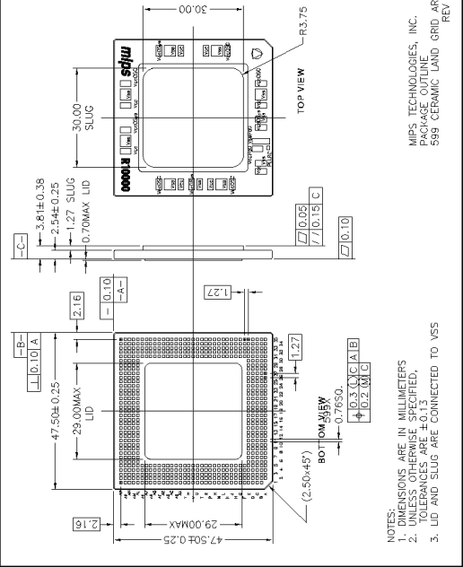


13.1 R10000 Single-Chip Package, 599CLGA

Assembly Drawings and Pinout List
The following pages contain a pinout list (Table 13-3), and drawings of an example R10000 LGA-PWB assembly, including details of the PWB, heatsink, and bolster plate. Actual hardware specifications are dependent on the user.
An assembly drawing of the 599LGA is also shown in Figure 13-2. Note that hardware specifications given in this drawing will require modifications to accommodate the actual dimensions of the socket, PWB, heatsink, bolster, etc.

Figure 13-1 R10000 599CLGA Package Outline


Copyright 1995, MIPS Technologies, Inc. -- 29 JAN 96


Generated with CERN WebMaker


